CAD TIPS

LAYERS

Use layers to communicate with yourself about what you’re drawing.

Some helpful tips:

Put the time in at the beginning to add and name the layers you’ll need.

Check your lines are on the correct layer by turning each layer’s visibility off one at a time.

Create a layer and name it “Archive”. Make it invisible. Instead of deleting lines you might want to reference later, move them to the archive layer for safe keeping.

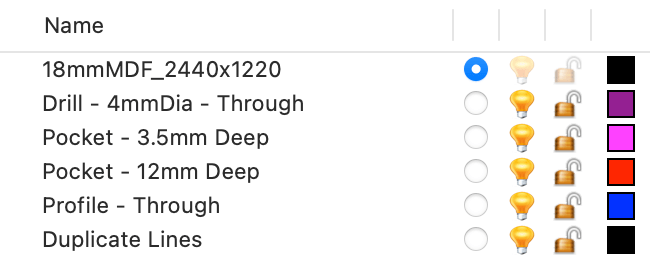
As a rule, each toolpath (profile-through, pocket 6mm etc) should have it’s own layer.

Layer formatting example for 3-Axis CNC flatbed CAD file

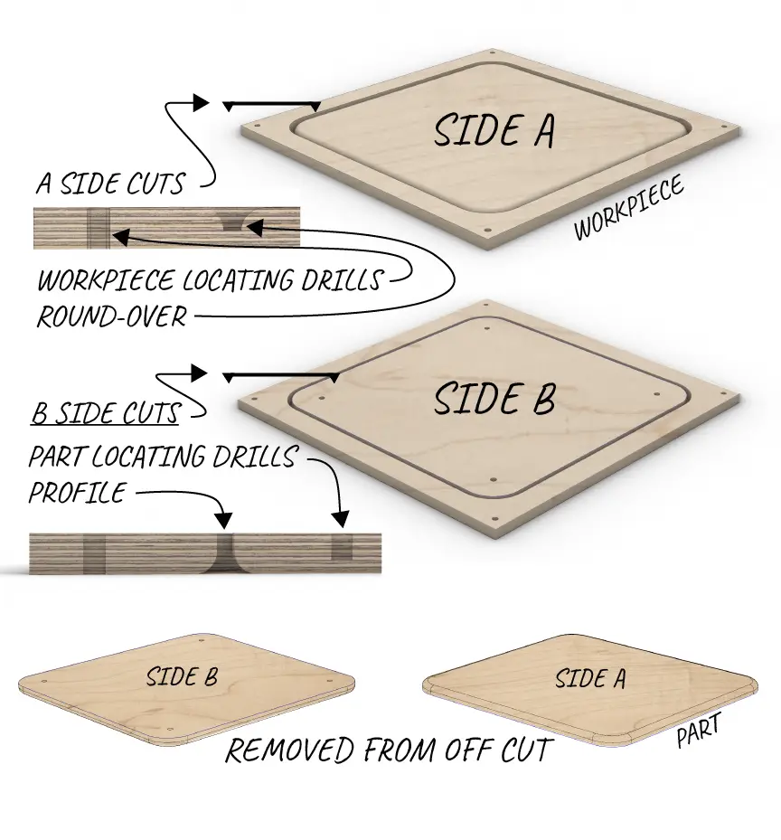
Double Sided Machining

Double sided cutting is achieved one of two ways:

Machine side A, remove from bed; Chuck some 3mm MDF on the bed. Cut out a suitable shape/template; Drop your workpiece in that cut-out, B-Side facing up.

Or with locating dowels, as illustrated. It opens up a lot of possibilities and can save a lot of labour down the track.

Get in touch to discuss which method best suits your job.

Double sided CNC machining diagram

NESTING

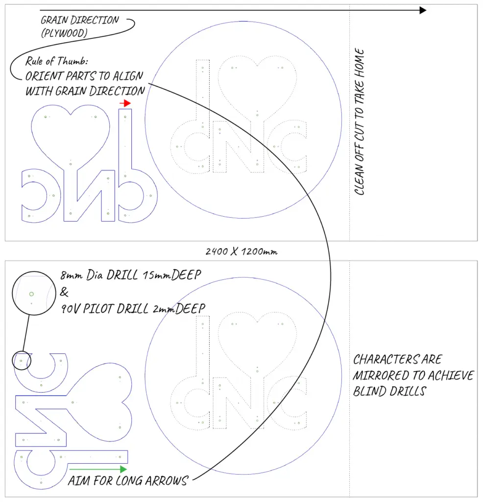
Nesting is the name given to arranging parts within your workpiece. Consider grain direction when nesting parts – it’s easy to forget when you’re at your computer.

Assume an East-West grain direction.

For best practice, allow 20mm between nested parts and 20mm at the edge of your workpiece.

Nesting and grain direction diagram for double sided CNC machining

INTERNAL CORNERS

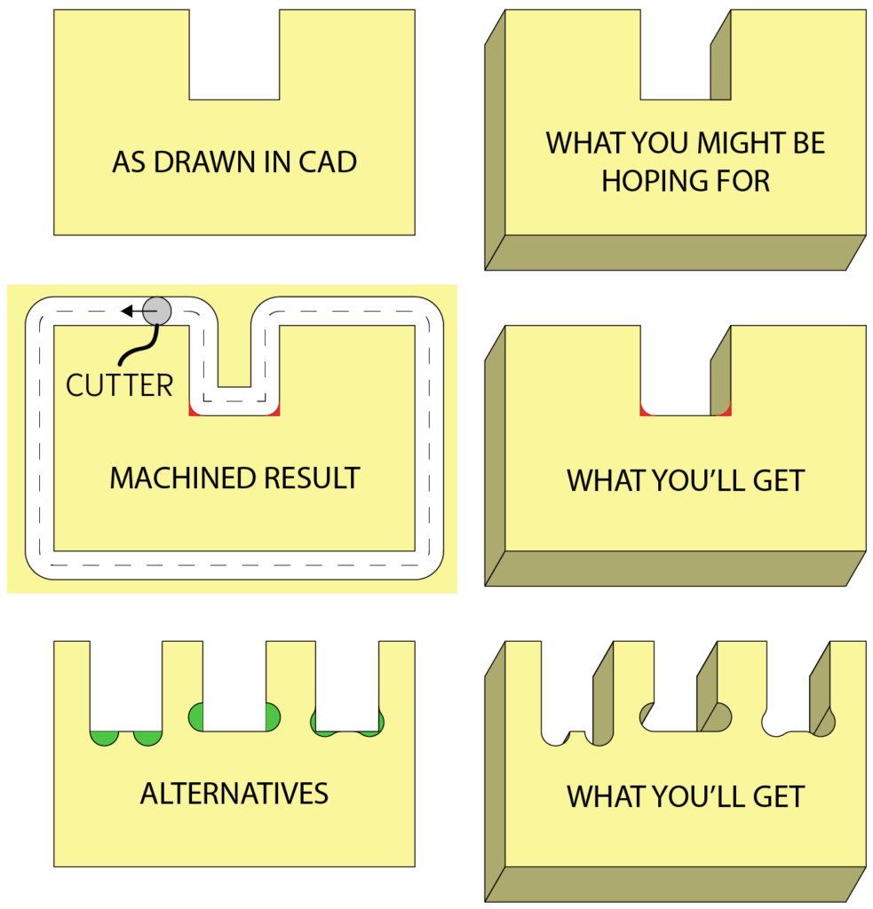
Every CNC router uses circular cutters. Circular cutters create square external corners. Internal Corners, however, will always have a radius. The radius will be equal to the cutter, as illustrated.

If this presents a problem for your job, get in touch to discuss your options. We’ve seen it all and we’re here to help.

Internal corners diagram for CNC routing
 

MATERIAL THICKNESS

📏 WHAT DO THE CALLIPERS SAY?

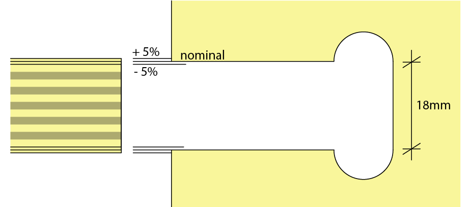
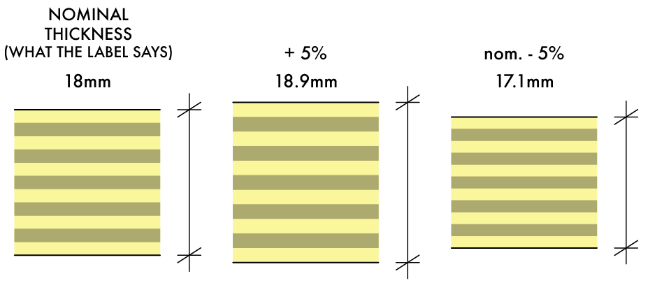
Treat nominal thickness dimensions (what’s on the label) with caution. 18mm plywood is rarely exactly 18mm thick. It’s usually pretty close and 5% off in extreme cases.

MDF is typically closer to the nominal thickness than ply. Depending on the job this might be a key consideration.

Let us know if this has the potential to create issues for you. We have practices to mitigate the risks.


Nominal thickness diagram
Nominal thickness diagram - section view

LOCATORS

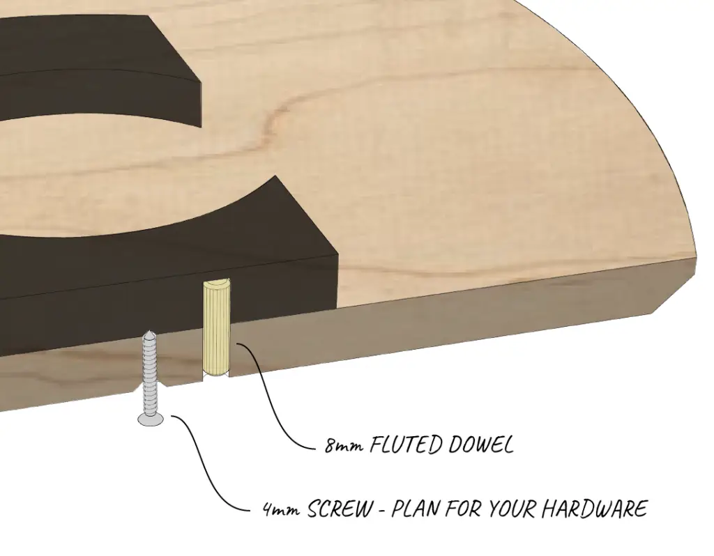
Locating Dowels are an indispensable tool to achieve the sign below.

Here we have:

  • Mirrored parts with blind drills.
  • Included pilot drills for screws. 
  • Made life easy with robust 8mm Harron dowels. Available from Bunnings.
Dowel located CNC routed parts assembly section